


The road geometrical model
Note:
Several elements in this model may not be fully available or operational yet (sideways, roadsigns). We'll do our best to deliver them as soon as possible.
Visualizing roads areas
The structure of a road is illustrated below:
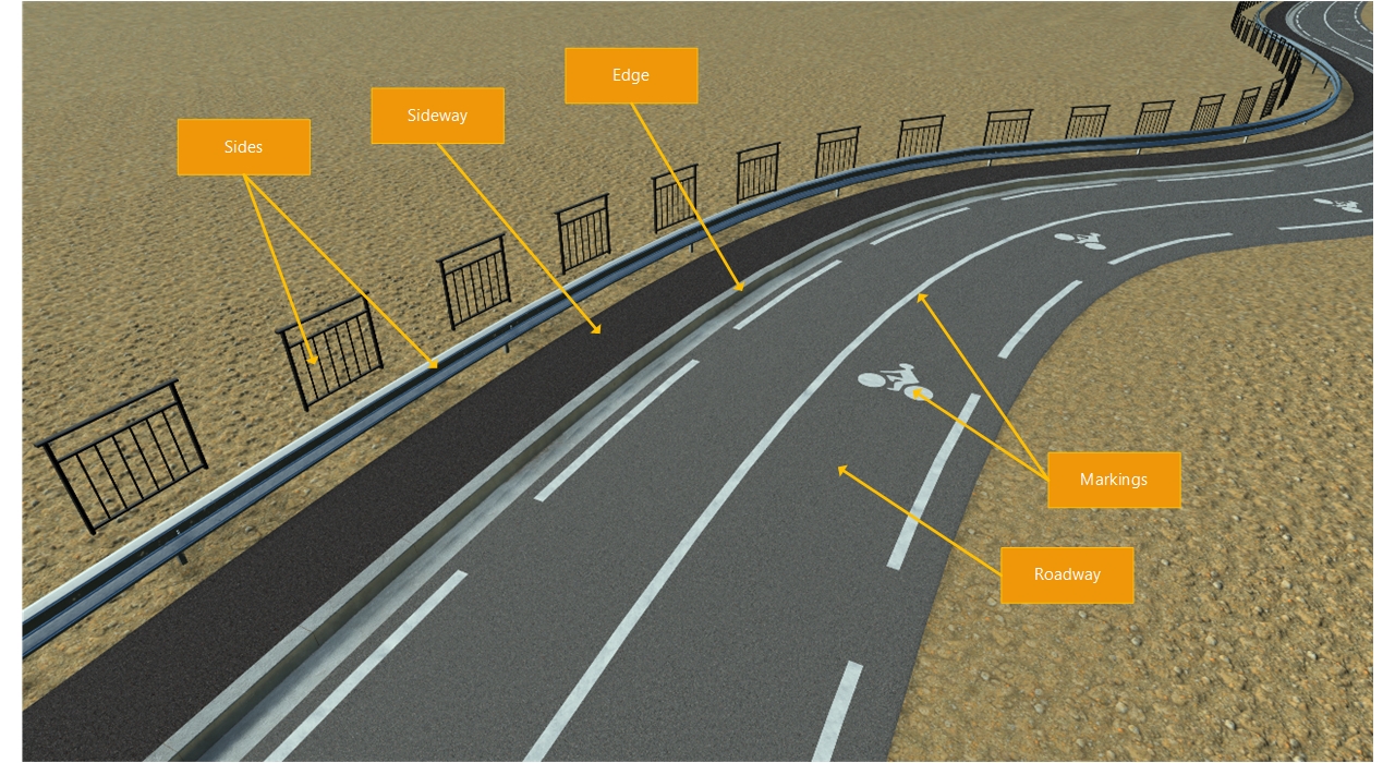
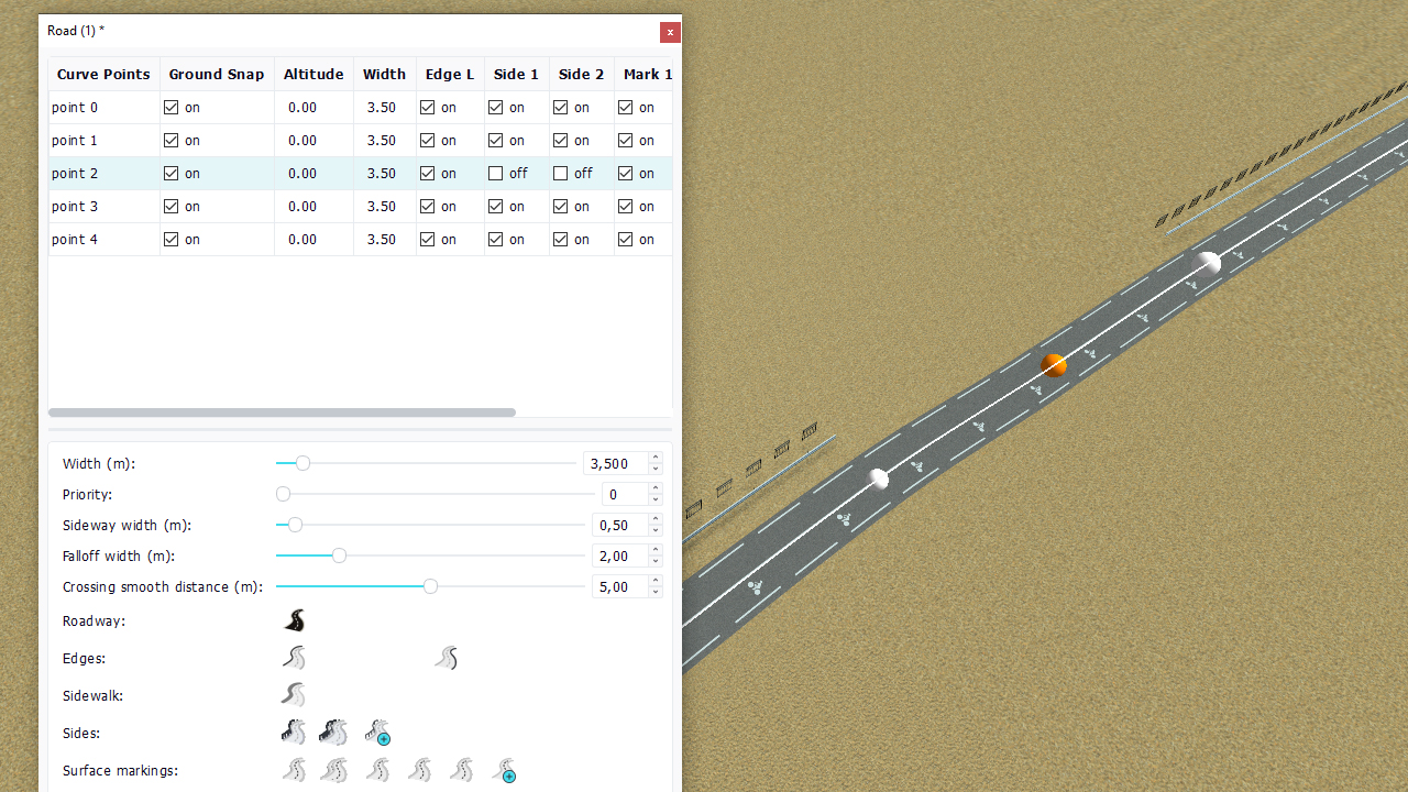
The road view has buttons that allow the control of every part of the road model. A word on each category:
- The roadway is defined by a material. This material is UV mapped onto the mesh of the road.
- Edges define the border of the roadway mesh itself. A road with no edge has a round cap to reach the ground while it ends up straight if it has an edge. This is illustrated in the picture below:
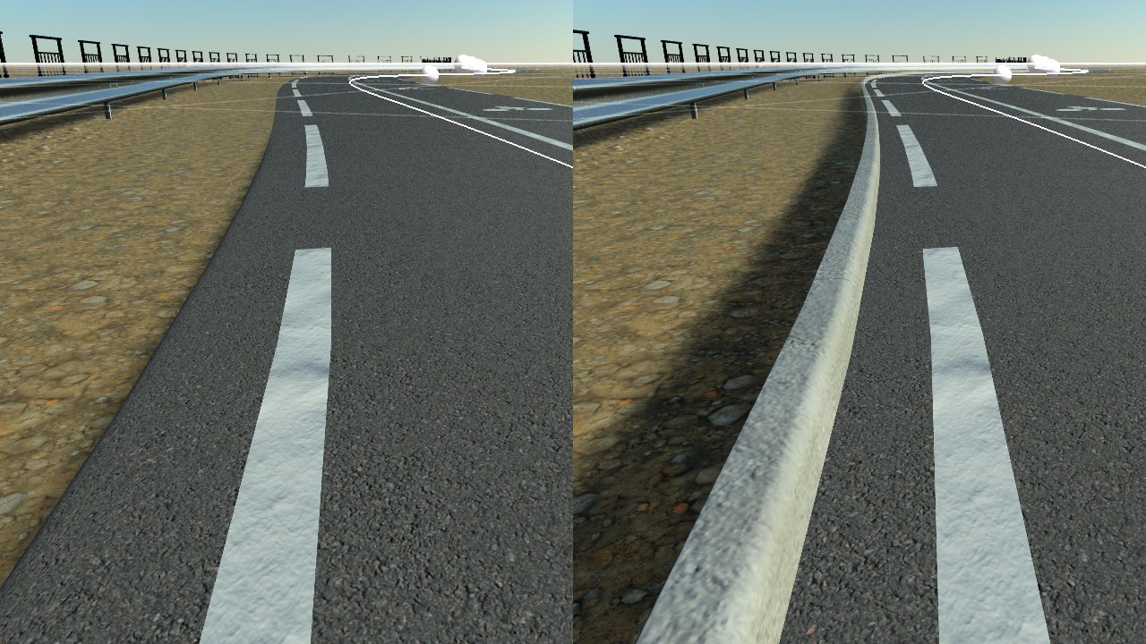
No edge on the left and an edge geometry on the right
A road that has no edge geometry is granted an extra 15 cm width for the round cap on its sides.
- Sidewalks are not usable yet. They'll define a walking area connected to the edge of the road and that'll get connected to buildings in a future version.
- Sides are extra geometries that can be added left or right of a road.
- Surface markings are defined by materials that are mapped onto extra meshes generated specifically for that purpose over the road.
- Bridge pillars are not available yet.
- Roadsigns are not available yet.
Edges and sides are using geometries and plain meshes. These meshes are lofted along edge paths. Roadway and markings are just using materials mapped onto the main mesh or ad-hoc polygons created purposely.
Defining a road geometry
A road geometry used in a network must be defined with the Z axis heading up, and must be defined to be lofted along the +Y axis as shown below:
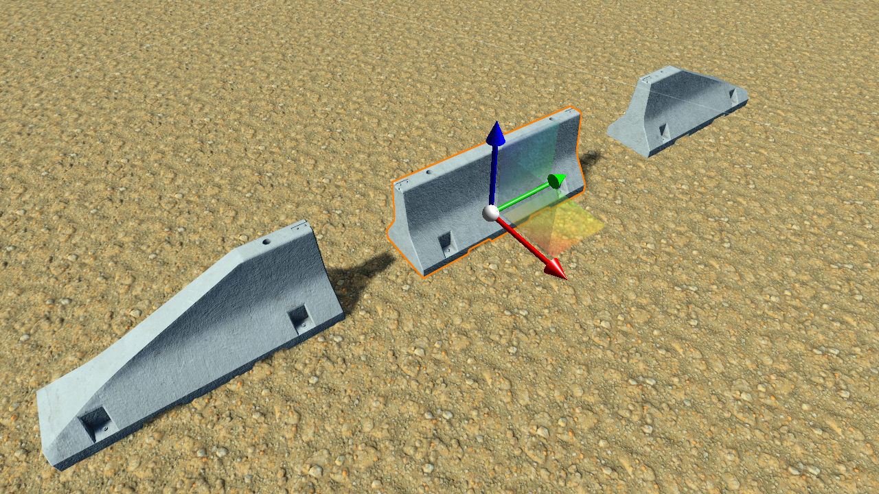
Up to three geometries can be used in the definition of edges and sides. A start geometry (used once at the beginning of the edge or side contour), a body geometry that gets repeated and an end geometry (also used once).
It's important to dimension these geometries usin a few meters per geometry as they'll get repeated an integer number of times to cover the edge contour they must adapt to. For instance if we have 100 meters of road to cover with geometries that are 5 meters long, we'll use 20 instances. If we have 99 meters to cover, we'll also use 20 instances of the geometries, but they'll get slightly stretched so that 20 x 5 meters = 100 meters is scaled to fit into 99 meters.
The system also avoids generating back flipped triangles for geometries that are too wide and follow a path curvature that is too high for their dimensions.
Using geometries or markings per road point
Side geometries and markings can be enabled and disabled per road point. This is illustrated below:
 Crossing roads Crossing roads | The roadway |
