


Bridge pillars
Bridge pillars are defined by three meshes: one base geometry, displayed once, a body geometry that gets repeated vertically and a top geometry that adjusts on the bridge deck with a vertical offset that is user controlled.

It's not uncommon to have the bridge edge geometries that enclose the bottom of the bridge, so that are used instead of the roadway bottom mesh. In the image below, the bridge section geometries help define a complete bridge in addition to the pillars.
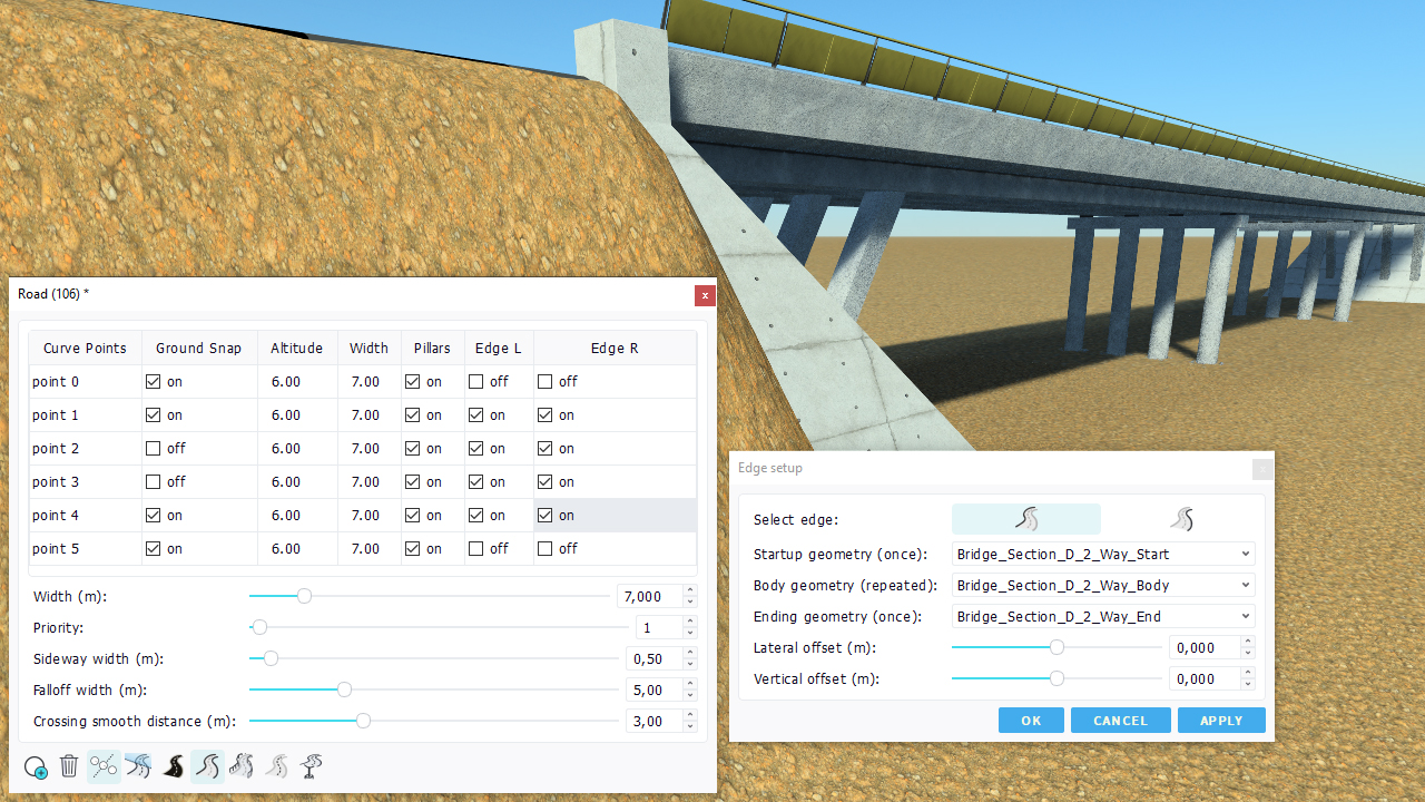
You can also see that the bridge section cover the area below the road:
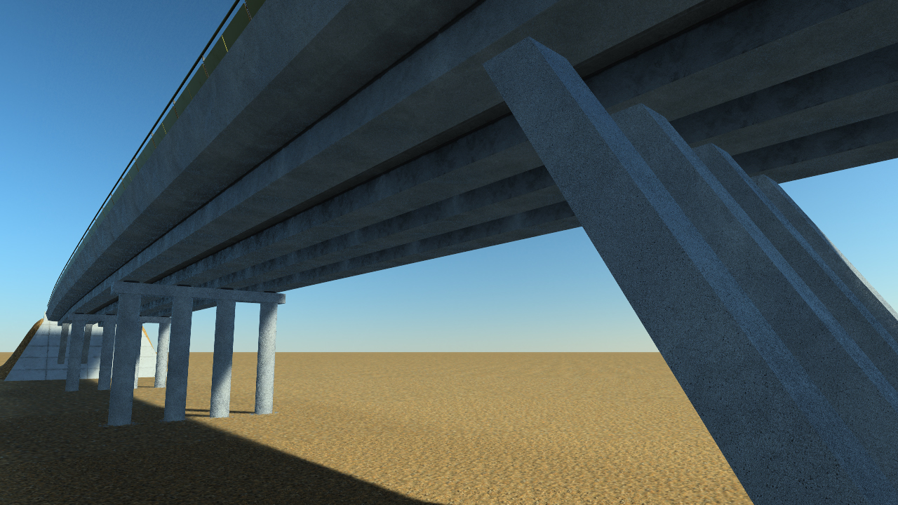
A consequence of this is that the bridge sides must have been designed for a given road width otherwise the connectivity of the side geometry below the road will not be ensured. In the image above, this is a 2 lane bridge for a 7 meters wide road that has been used. The bridge pillars is made of 4 concrete cylinders.
 Roads surface markings Roads surface markings | Creating roads templates |
