


Roads
Roads are important city parts, obviously, without which access to other city parts could be quite challenging...Like most city parts such as buildings, roads can be generated from Blueprints when importing cartography data.
Roads are based on curves, that can be polylines or Bezier curves.
Curve points properties
Unlike most other city parts, roads points have important properties that'll modify the design of the surrounding landscape. A road curve point has the following parameters:
- Ground snap: Snapped onto the ground. When so, on a city refresh, the point will be set on the ground.
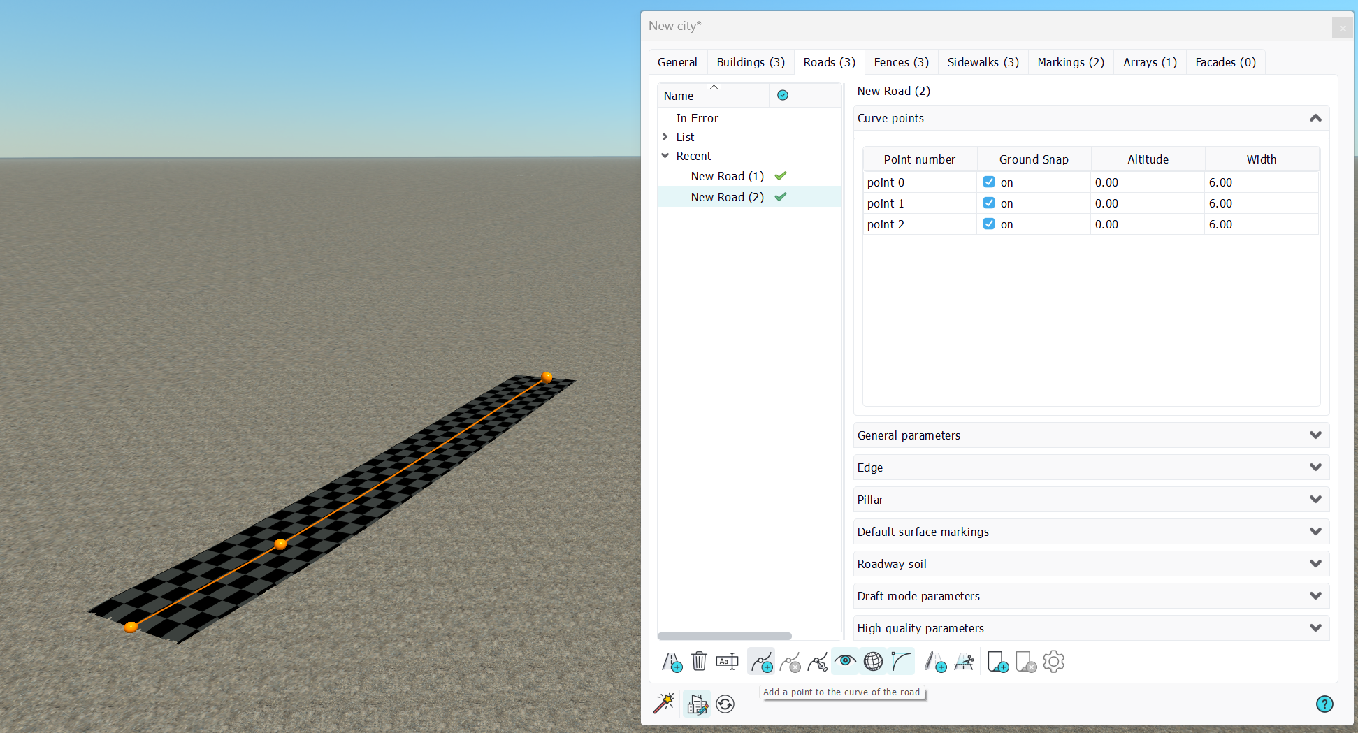
- Altitude: The point is set on the ground and an extra altitude can be added to it. This allows carving roads that carry their foundation layers upon modifications. This is illustrated below:
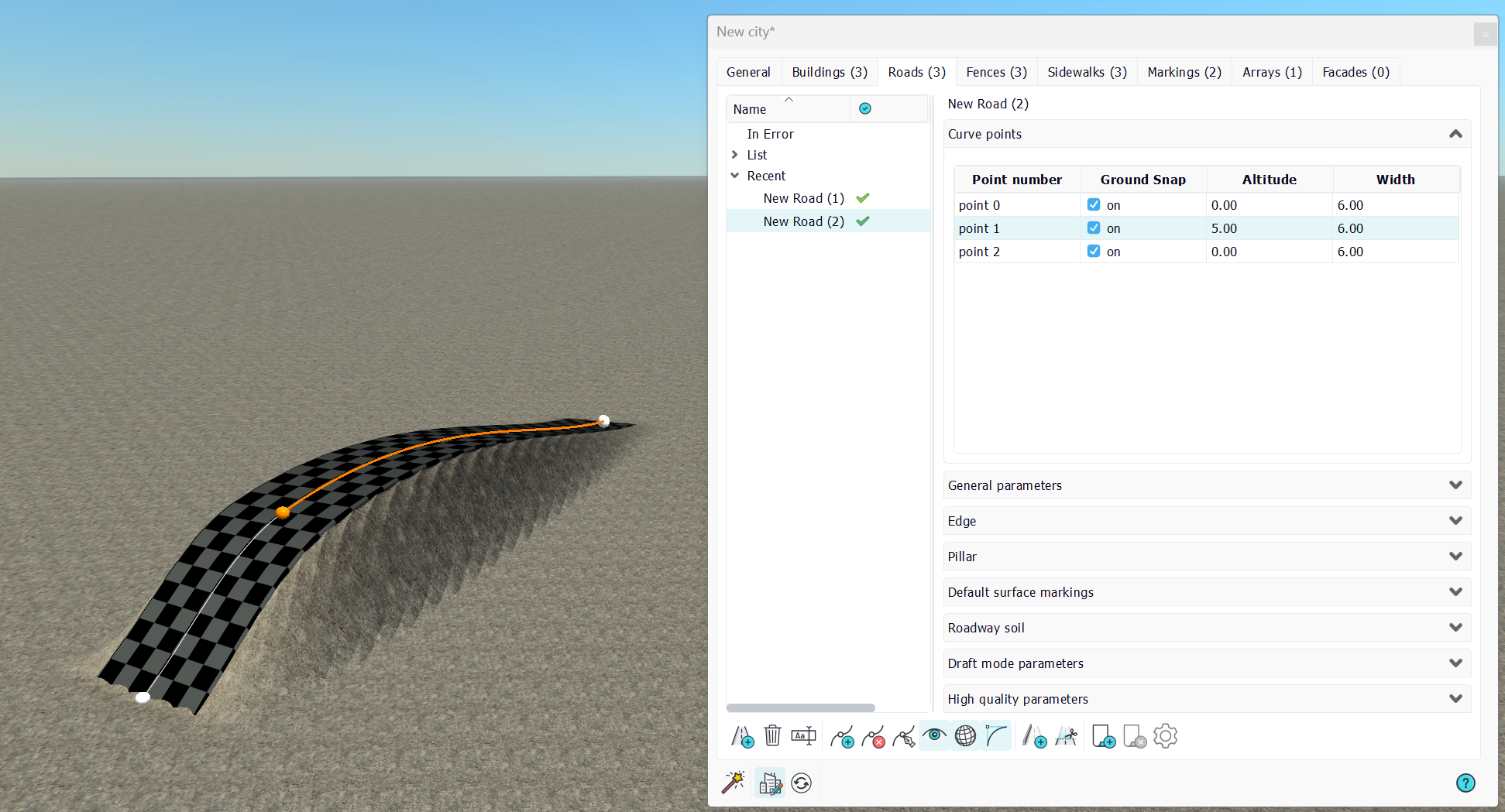
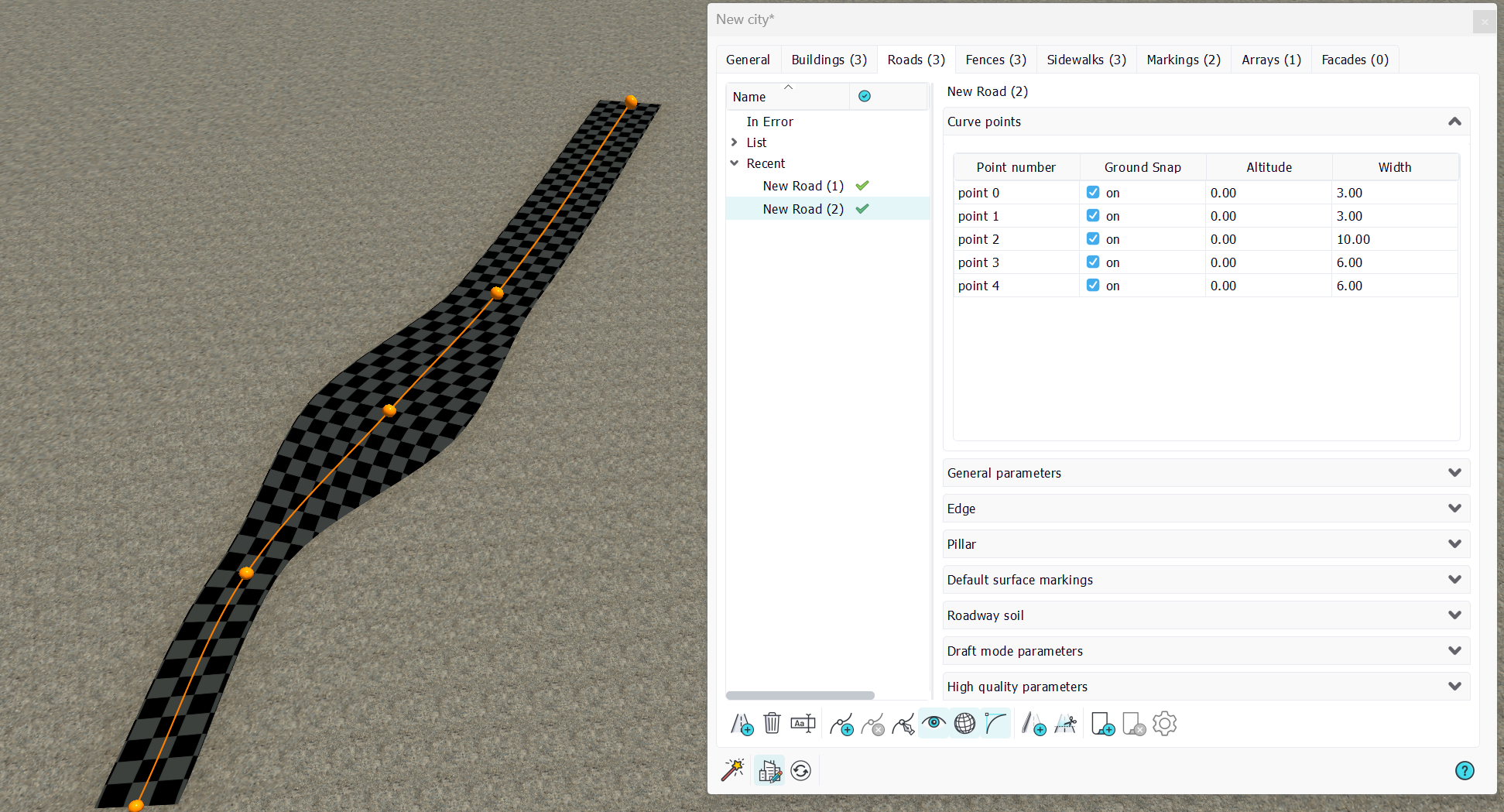
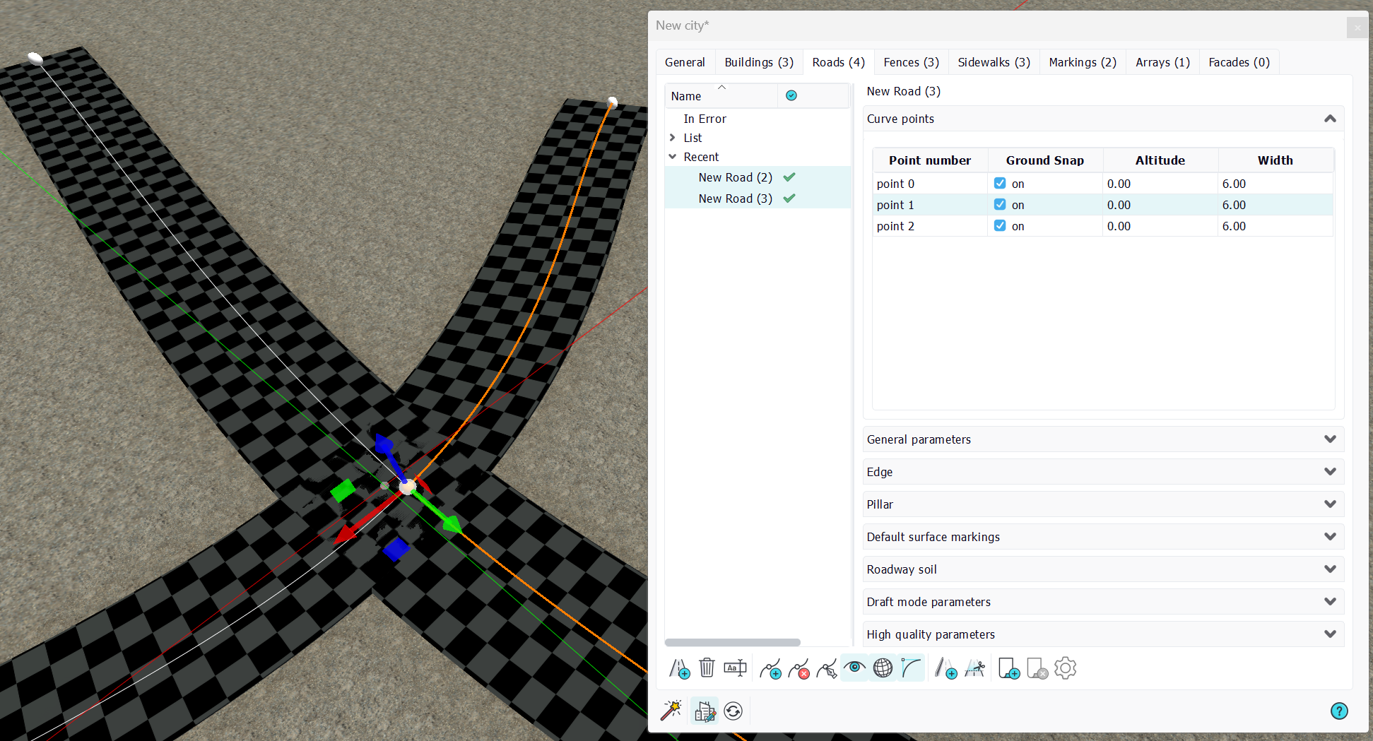
The altitude of the second road point has been raised to 5 meters. Consequently, the road path itself is up 5 meters and the ground is set to adapt to that change. On the other hand, if we remove the ground snap flag from the road, we'll create floating roads, that'll be used for bridges:
We have added two more points with ground snap before and after point no 2 whose ground snapping has been removed. We can see that the first road segment 0-1 and the last 3-4 are "grounded" and carve the underlying terrain, while the two segments 1-2 and 2-3 that are connected to a road point which isn't snapped are without ground sculpting.
Then, we can also control:
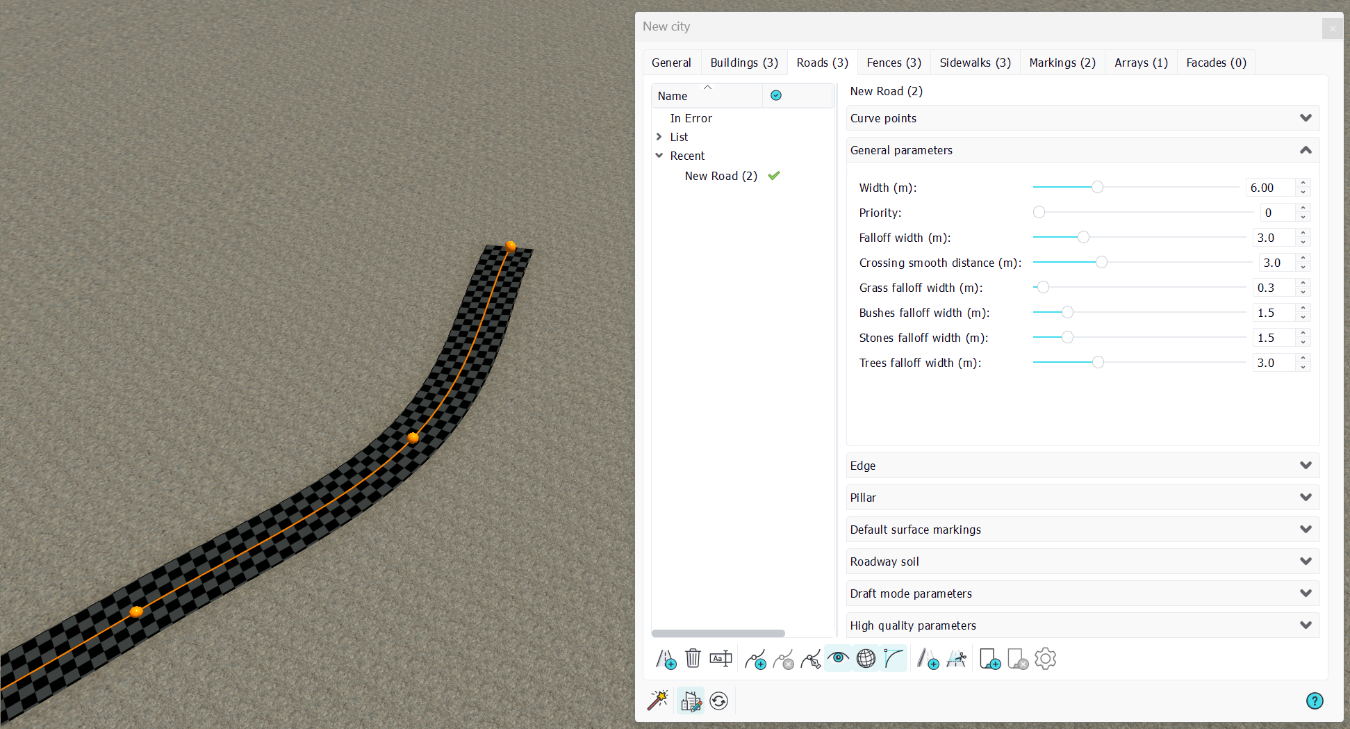
- Width: The width of the road at that curve point. When a width difference exists between two roads curve points, an interpolation takes place, as shown below.
Curve general parameters
Roads general parameters are about the behavior of the road when involved into a crossing and about its behavior against surrounding vegetation. Among these:
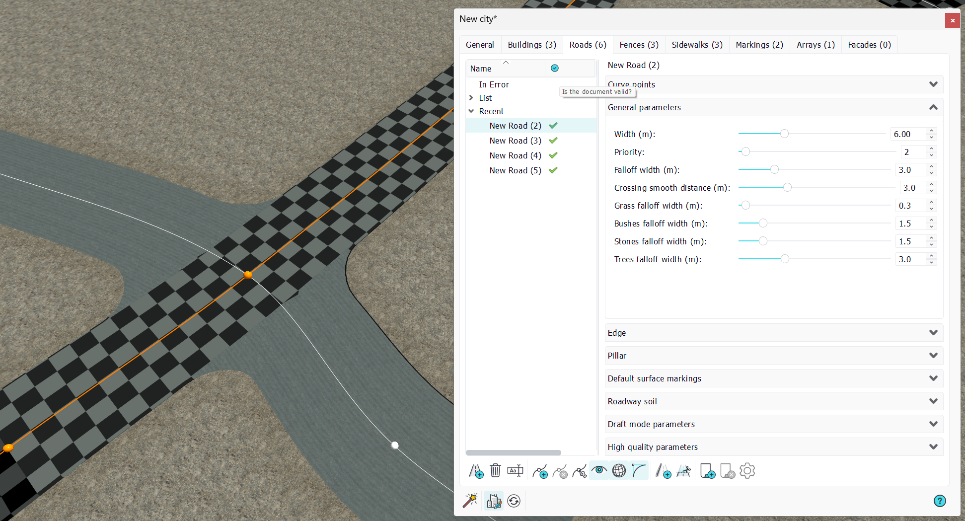
- Width: Is an indication of the global road width. This parameter is not necessarily applied to the entire road. However, changing its value will raise the following prompt:
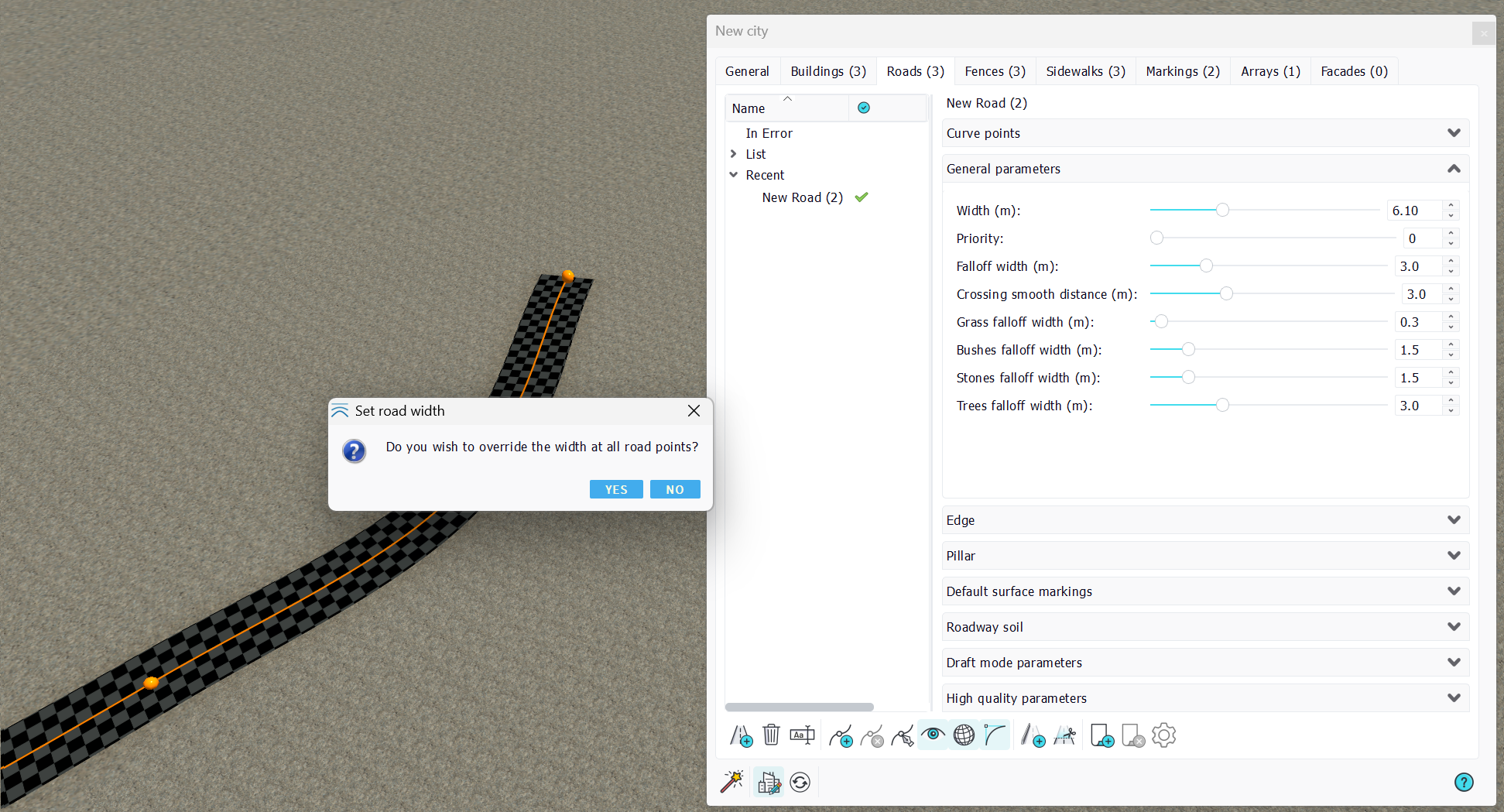
On pressing 'no', the operation has no effect, while pressing 'yes' it will override, in the curve points properties, the width of every point to the selected value. In that later case, changes made with different widths at road curve points will be lost and all widths will be made homogeneous.
We'll then detail the road priority and crossing smooth distance in the paragraph below:
Creating roads crossings
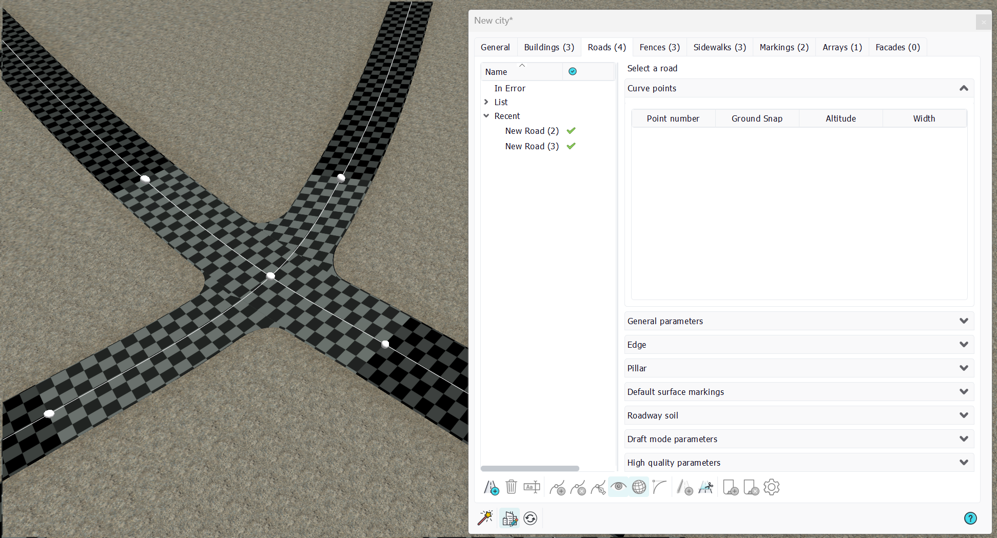
Roads crossings are created by the overlapping of two roads points. That overlap must be exact, in a sense that two very close points don't make a crossing. This is illustrated below:
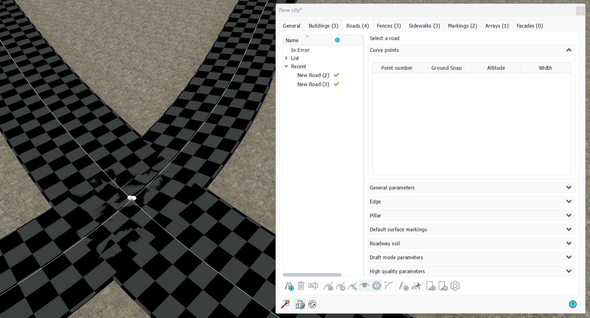
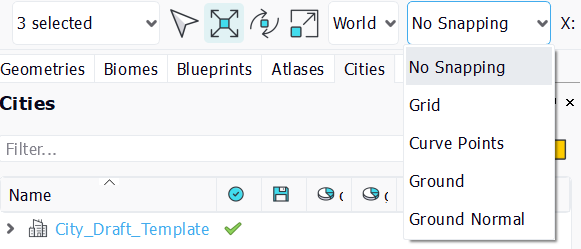
The two points are not located at the exact same position, hence there's no crossing created and we have two roads that interfere badly, creating visible stitching artifacts. To ensure that the two roads points are at the same location, you can either snap to some grid points, or set the 'snap to curve points' in the selection toolbar:
A trick to make sure all the points are merged is to select them and move them. All of them should move as in the image below:
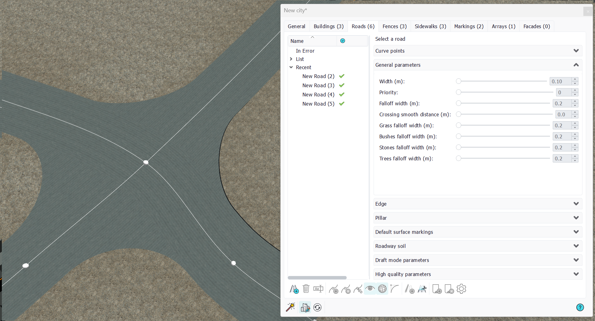
Then, once snapped and the city refreshed, you should see a 'real' crossing:

Something worth noticing is that the color of a crossing is not the same as the color of a plain road. The greyish tone is lighter. We can see that below:
Crossings are handled a bit differently than regular roads segments in the sense they interact with all other roads segments connected to them. Some crossings can even be extended in complex situations so that the road topology calculation remains correct:

Then, back to our general roads parameters, the road priority is a value that allow one road to overlap others during the display:
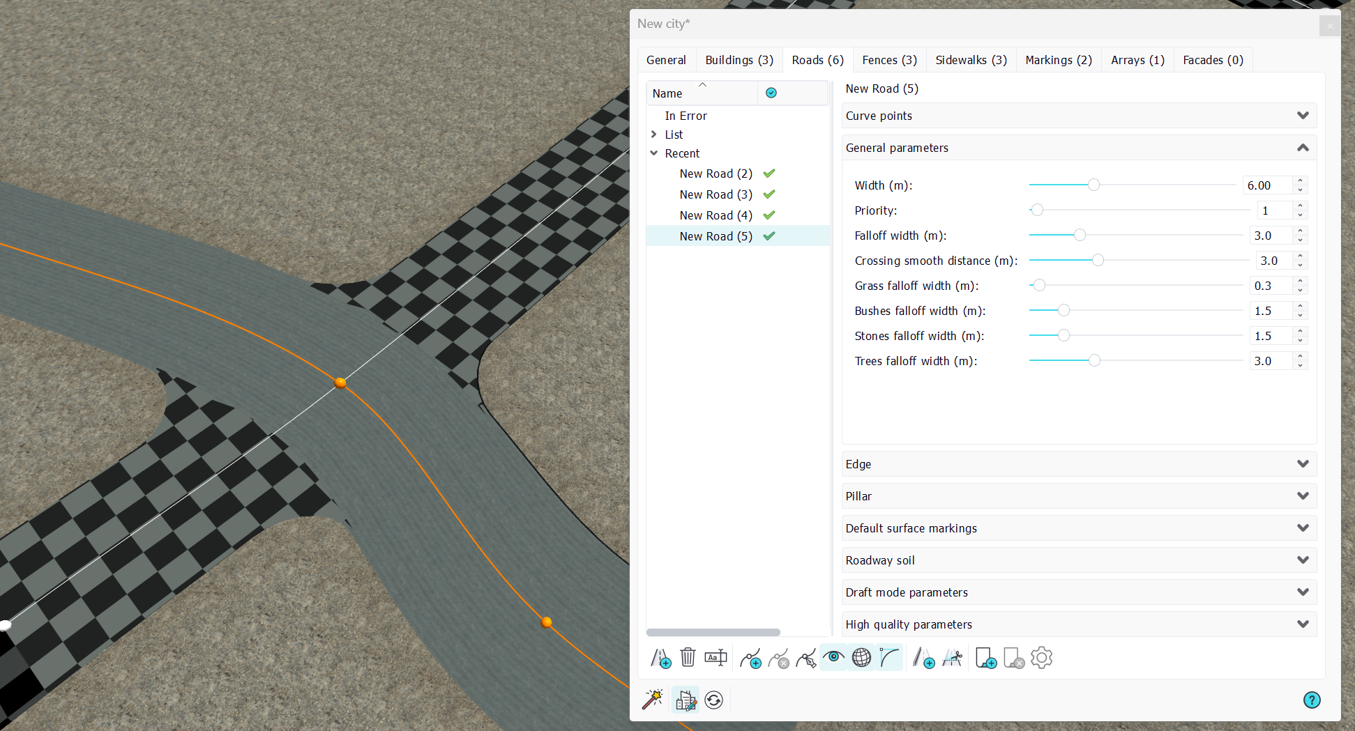
Setting the selected road (that has a draft pavement applied for an easier understanding) priority to 1 will have it 'win' the crossing. Setting the other road's priority to a higher value makes it 'loose' the crossing:
The 'crossing smooth distance' is a joint parameter for crossings. If defines the roundness of roads at the crossing. The smaller value of all roads at a crossing are retained to define the smoothing that takes place at a crossing:
Hence, to increase the smoothing at a crossing here to 10 meters radius, both roads should have an increased 'crossing smooth distance' to 10 meters.
Curve general parameters (continued)
The 'falloff width' is a similar parameters, but that affects the size of the ground sculpting of the road, as well as all the vegetation falloffs distances:

The falloff is only visible when the road is not sticked to the ground or if the ground's relief hurts the road paths in which case the road will carve the ground, and smoothly integrate into its surroundings thanks to its falloff width.

Roads edges
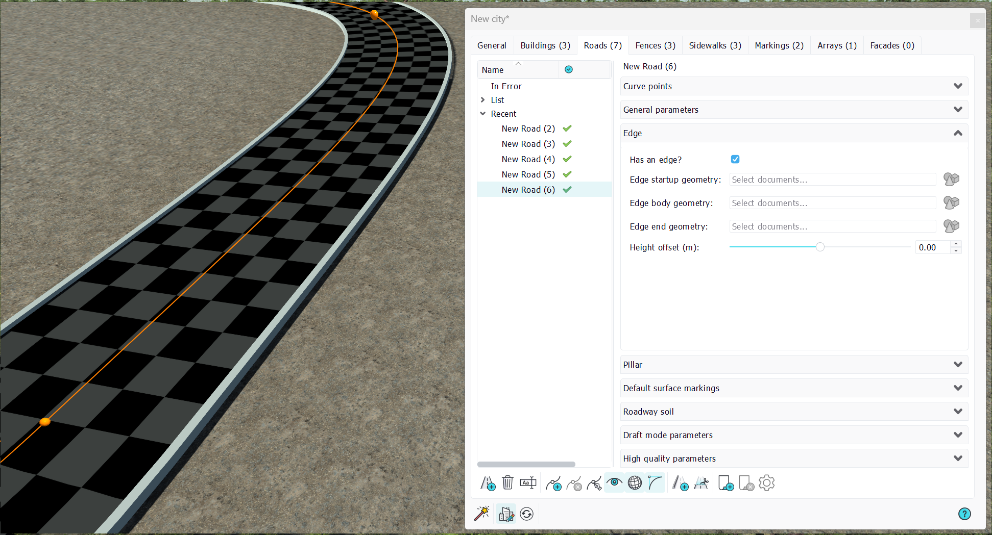
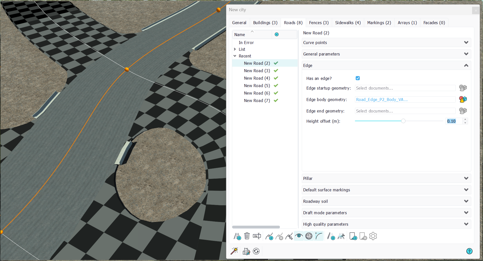
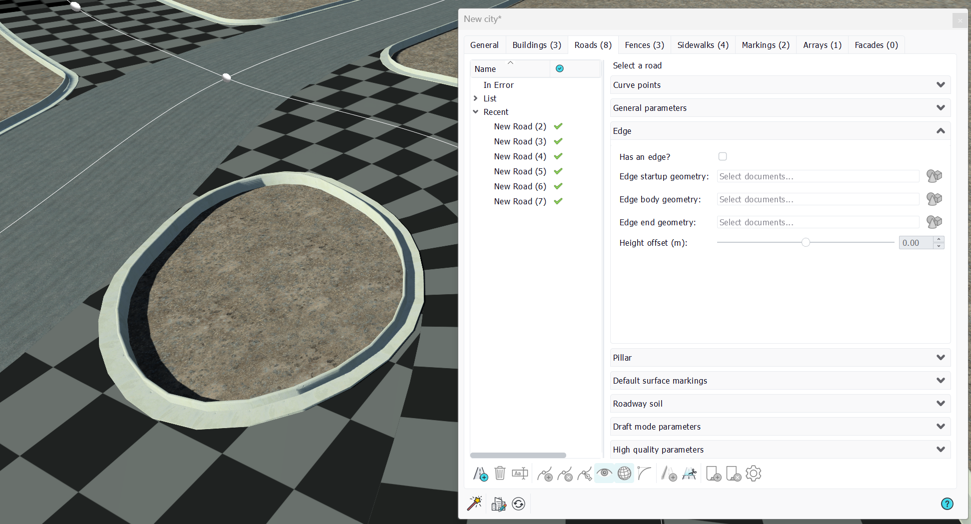
A road may have a border edge, which can either be a simple block in draft mode or a complete geometry in high quality mode, allowing the city to have clean representations of its roads and sidewalks:
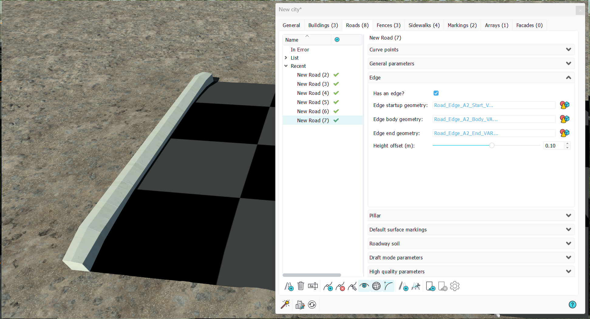
Note that the road edge is taken into consideration when a sidewawlk interferes with the road:

Here, we see that the road edge body has been adjusted 8 cm above the road base level, and perfectly connects the road and the sidewalk. A road edge can also have start / stop geometries in case we have road endings to handle:
Roads edges in crossings
The setup of roads edges in crossings may be a bit tricky in the sense that to get a consistent result, all the roads that are part of the crossing should have the same edge:
Assigning the edge to only one road in the crossing can lead to inconsistent, unpleasant results, while assigning the same edge to everyone there will make the result look good:
Roads pillars
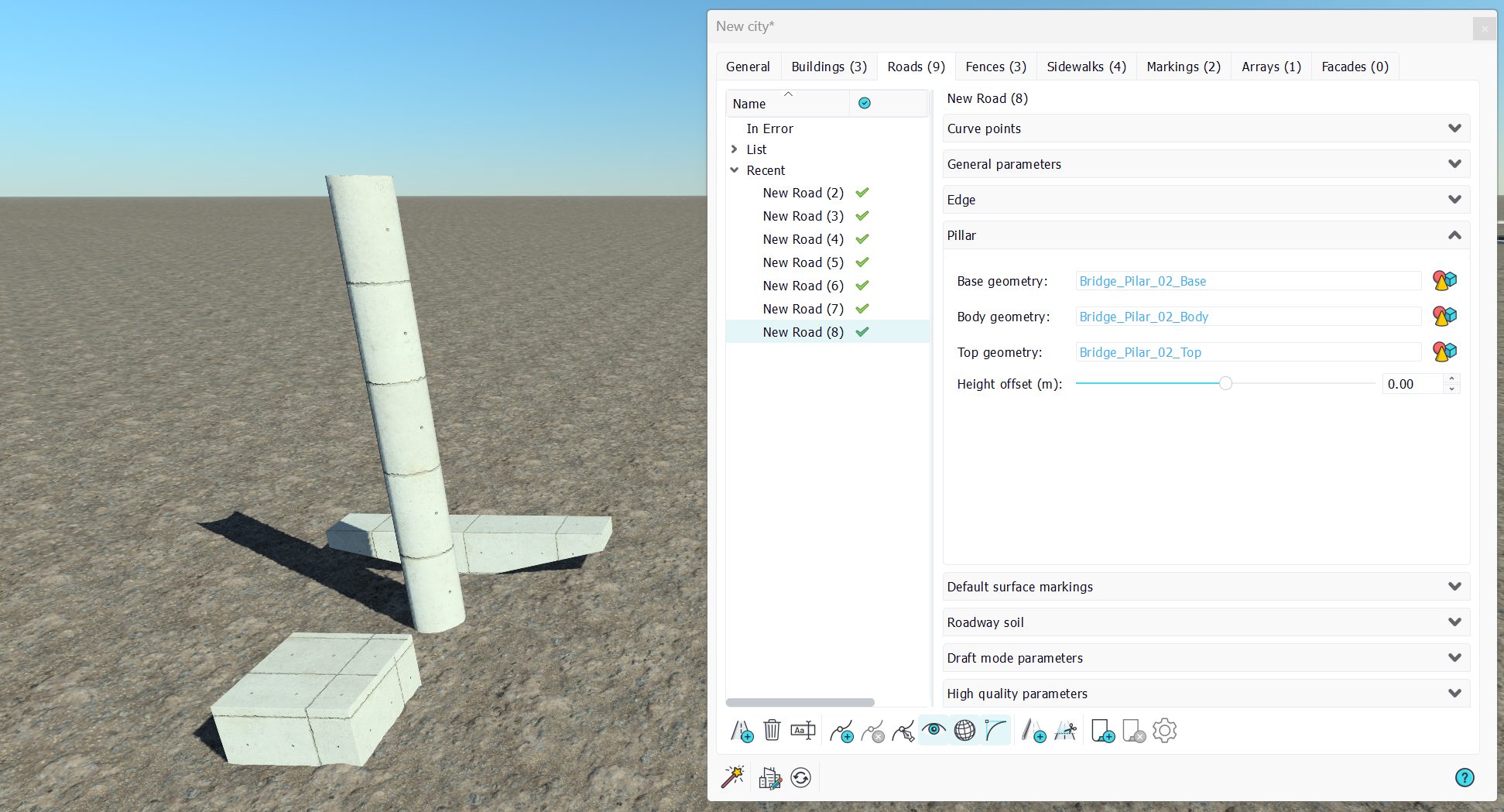
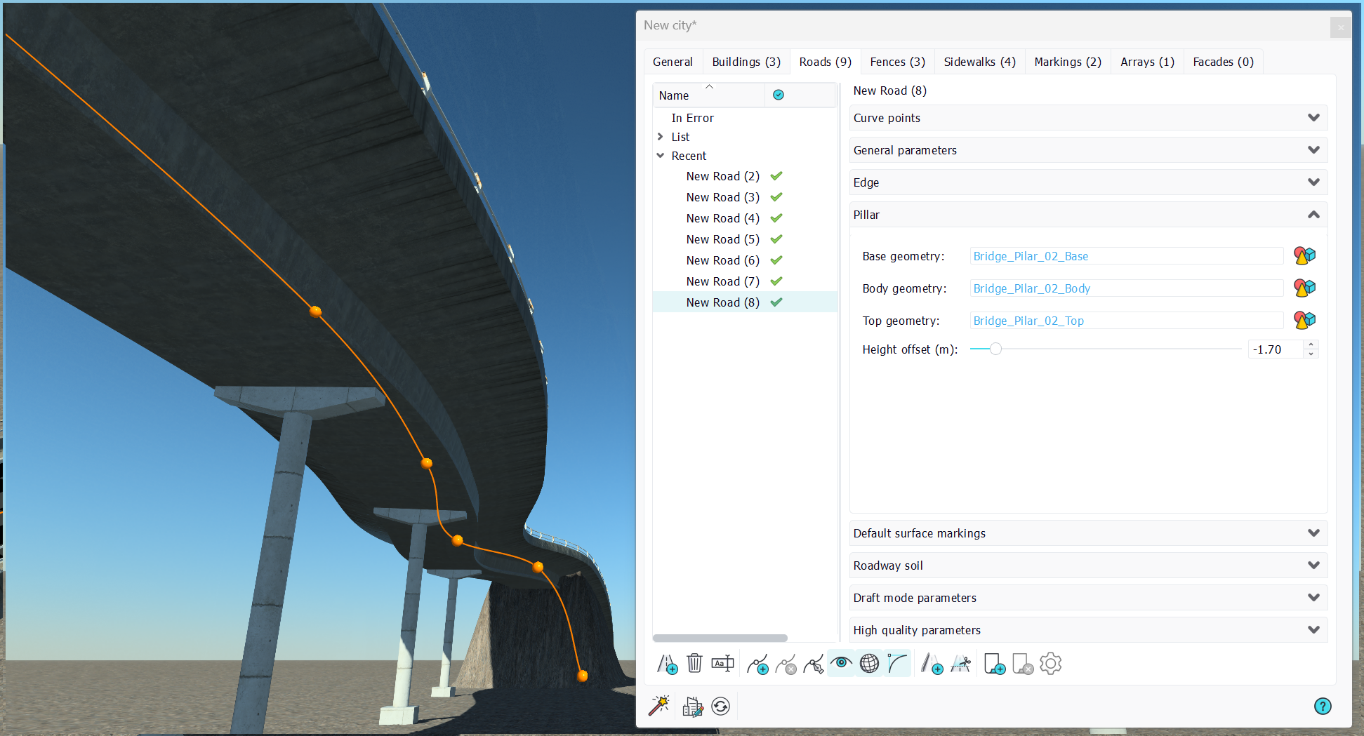
We have seen that a road can have some of its segments floating above the ground when the ground snap option of a curve point is turned off. We use this to define bridges, and we can setup pillars to support bridges, as shown below:

A bridge pillar has three parts: a base, a body (that gets repeated to reach the road height from the ground) and a top. Details of the pillar we've been using are shown below:
A road pillar in itself is not enough to define a bridge. Bridges are relying on edges as we'll detail below.
Using roads edges for bridges

NDunes has specific edges geometries that can be used to define bridges. These edges must have a bottom cap closed and are generally defined for a given road width. This means that an edge that has been defined for a 6 meters wide road will not work properly on a larger road. Below an example of this problem:
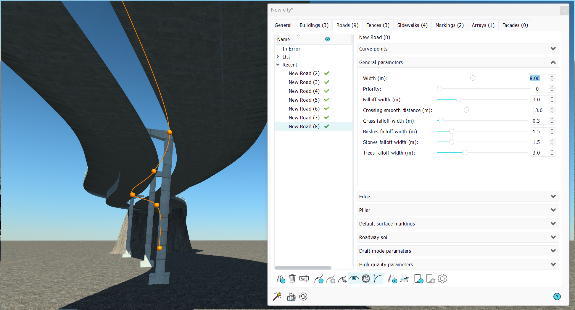
The chosen edge for the bridge was meant for a 6 meters wide road. So when the road fits the chosen bridge, the shading works and we can adjust the pillar vertical offset:
Default surface markings
The road provides some default surface markings which are simple lanes. This is shown below:
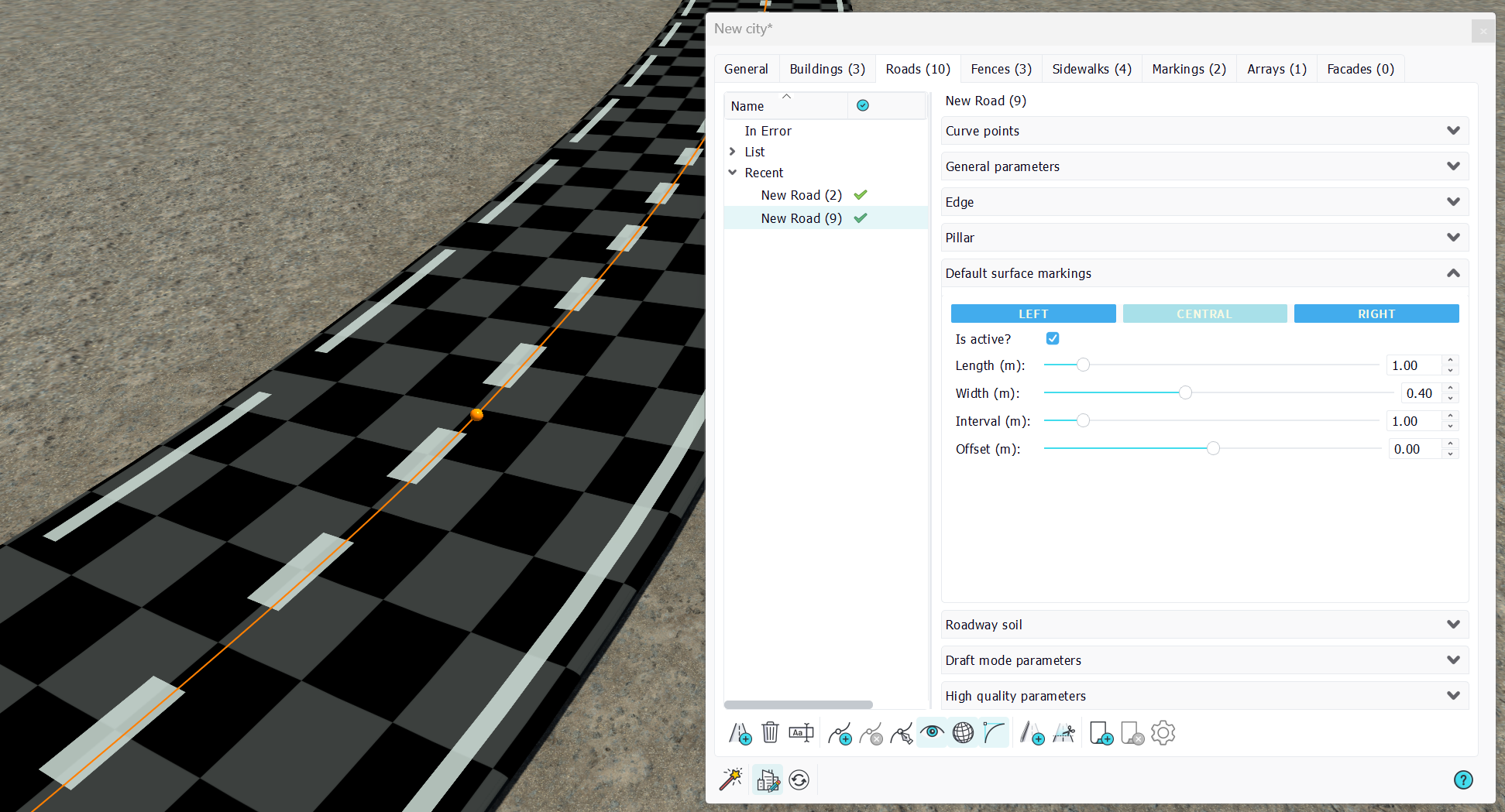
These markings will follow the road path. Unlike Markings which are static, these are linked to the road. Shapes are quite simple:
- Is active?: A marking activation flag. We have three default markings, left, central, right that can be activated separatedly.
- Length: Length of the marking in meters. Along the road path.
- Width: Width of the marking in meters. Perpendicular to the road path.
- Interval: Distance between two markings.
- Offset: Allows shifting the marking left or right of the road. Negative values go inward the road for left and right markings while negative is left for the central marking.
Markings are rendered with a default white decal material in draft mode, while they can have a specific marking material in their high quality parameters.
Offset the road to create another part
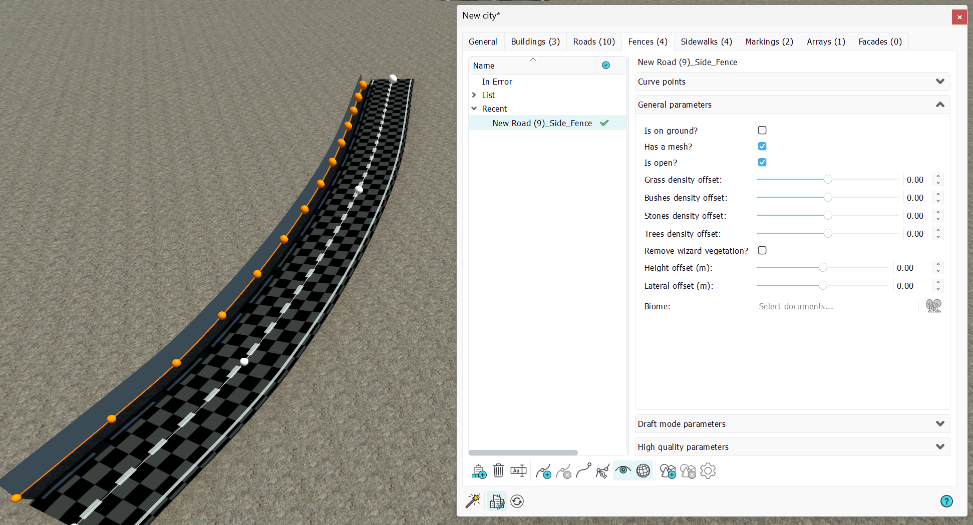
From the paragraph above, we may need more markings or more objects related to the road itself. For instance if we want to create a barrier or to add roadsticks along the road on one of its side, we have a handy tool that can be used to create another city part from a road. This is the side object creation tool for roads:
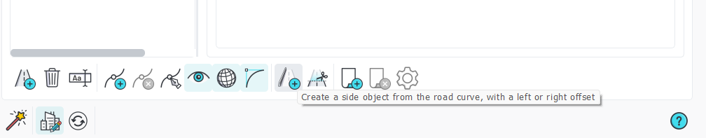
Launching the tool will propose you some choices:
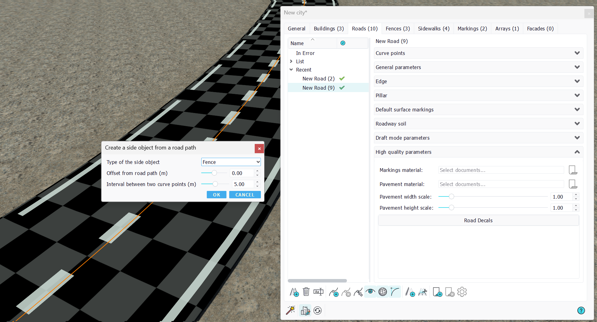
Several objects can be created from a road: Fences, Markings, Arrays or Roads. Select the distance from the road path and the interval between two points in the created side object. This interval will define the accuracy of the resulting curve. Since the source road curve may have very few points and may be a Bezier curve, creating another side object with a lateral offset without ensuring that we have a regular sequence points will not provide a constant spacing from the originating curve.
Here, we create a fence 4 meters left of the source road:
Cutting a road
The toolbar has an icon with scissors that can be used to split a given road in two parts.
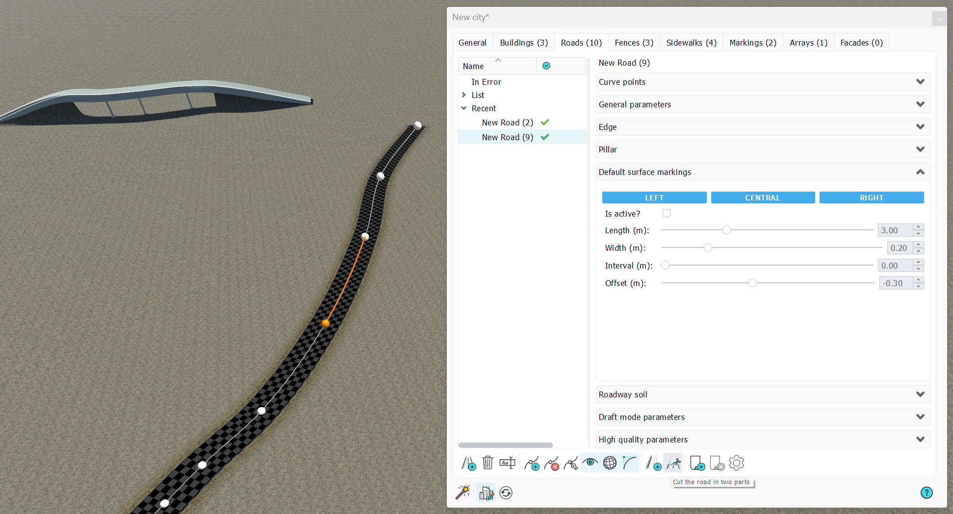
Select a curve point and press the button. This will create two road parts. The first one keep the source road name and the second receives a '_tail' suffix name.
The roadway soil
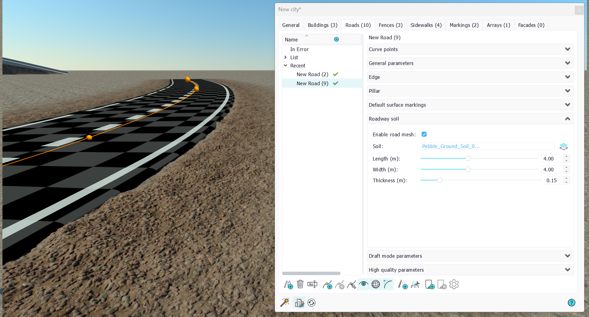
The roadway itself can have a side soil which depicts the earthwork around the road when its constructed. We can see ballast, cobblestone or whatever appropriate. On setting up a roadway soil, we'll see that soil around the road at a distance equal to the road falloff width (see in the Curve general parameters (continued)). Soil parameters can be adjusted and are initialized from the soil default mapping dimensions.
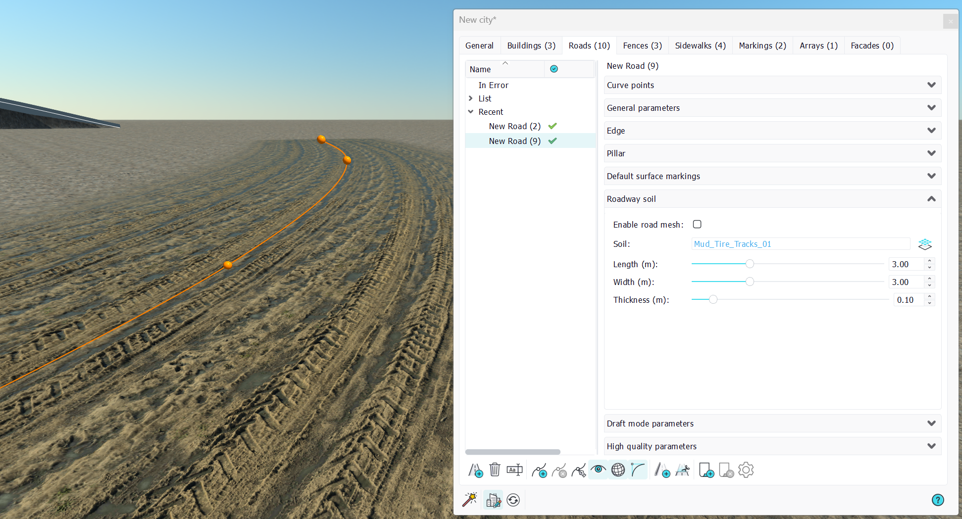
In addition, the soil section of the road allows to turn off the roadway mesh. This is very useful when a non-asphalt road path has to be rendered, such as tire tracks in fields. Here's an example below. Simply turn off the roadway mesh and refresh the city:
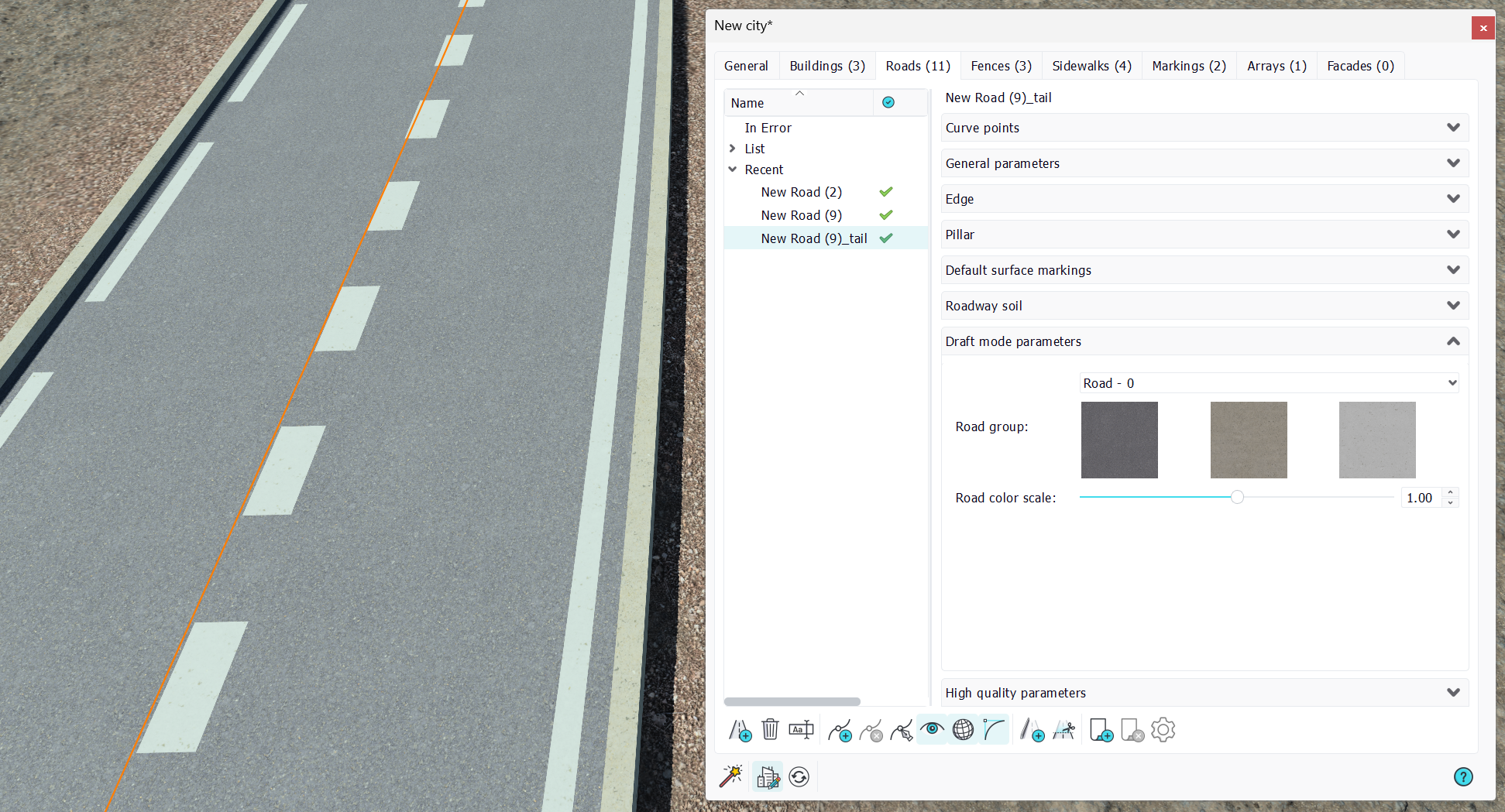
Draft mode parameters
Draft mode parameters of roads are pretty straightforward: select a facade group to be applied to the road. The facade group has three items:
- The pavement texture image: this is the texture mapped onto the roadway mesh
- The concrete texture image: this is the texture mapped onto the edge of the road if it's setup.
- The markings texture image: it's applied to the default road surface markings.
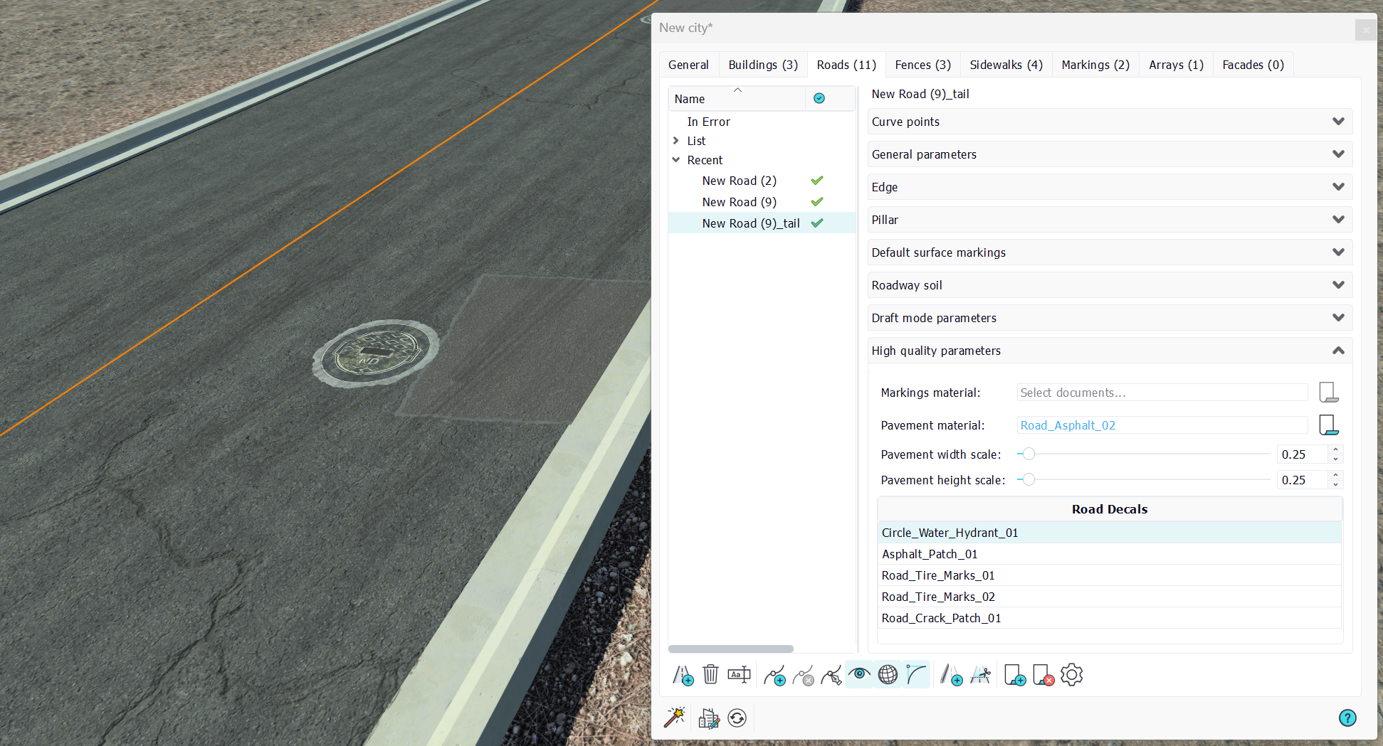
High quality parameters
High quality parameters of the road are threefold:
- A high quality material that can be used for all the road default surface markings.
- A high quality material that can be used for the road pavement. We'll often use asphalts based materials of some kind there. We can adjust the size of the mapping of that material onto the road by scaling it alongside the two road dimensions.
- Road decals: Road decals are scratches, manhole covers, tire tracks, and all details that bring realism to the road.
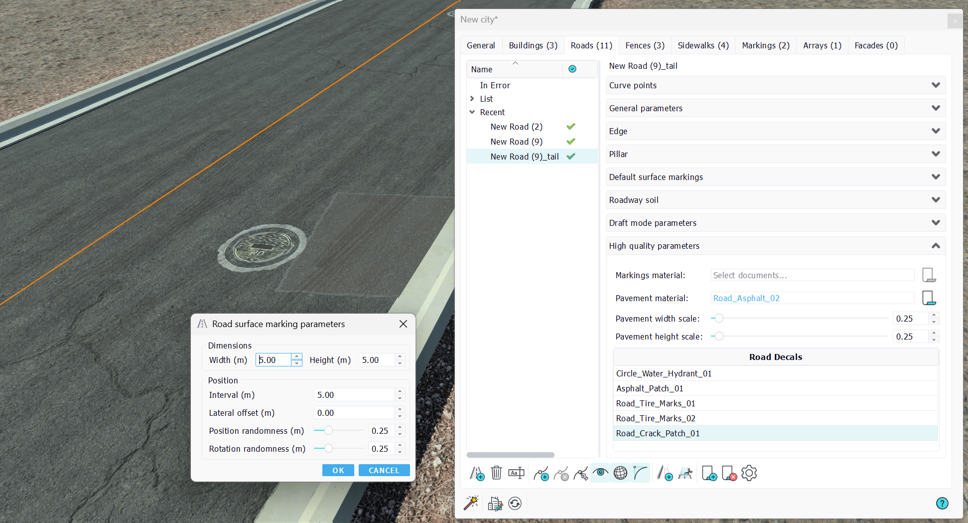
Roads decals
Roads decals are materials that can be dropped from the material tree view onto the road directly. Note that they can be also added or removed manually from the road toolbar.
Parameters in a decal are useful to replicate the decal along the roadway path. We can control the dimensions of the decal and its position along the road. The interval and lateral offset values are randomized using the specified randomness, so that a high randomness can easily break patterns and make the road appear more realistic. Like default markings, decals will follow the road when it's modified.
 Buildings Buildings | Fences |
