Decals
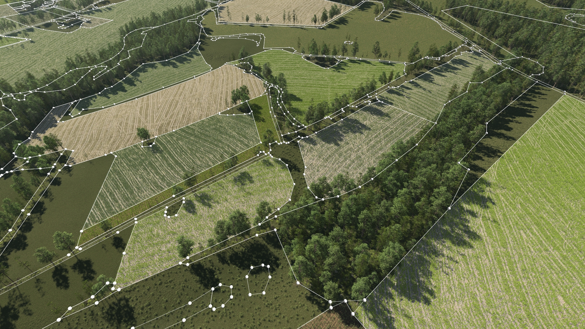
Decal documents consist of a group of several areas defined on the ground, onto which you want to apply some local modifications. For each decal area, you can modify the soil, the plant densities, the elevation, etc..., which enables you to customize it.
Creating a decal document
To create a decal documents, open the decal treeview. Then create a new decal document, name it, and drag & drop it to the current scene. You can double clic on the document to open its view.
The view of the decal document is divided in two sections :
- On the left part, an ordered list of all the decal areas contained in the decal document.
- On the right part, the properties of the selected decal area.

Creating a decal area
Once your decal document is created and placed in the current scene, you will want to create your first decal area by clicking on the "Create a new decal area" button at the bottom of the area list. A new area will appear in your list.
To define this new decal area using some curve points, you need to :
- Select this decal area in the list. It will be highlighted in a light blue color.
- Toggle the "Add new points" button.
- Start adding new points to the decal area by left clicking, in the viewport, on the ground. A new curve will be created with your points.
- To stop adding new points, click again on the "Add new points" button to untoggle it.

You can delete decal areas or curves points using the trash bin button. Select the object that you want to delete in the decal areas list view or in the viewport, then click on the delete button.
You can change the way points are added to an existing decal area curve. We have two modes defining how a new point is added to the existing curve : "Continuous contours" and "Closest Segment". You can switch between the two modes using the button next to the trash bin.
- Continuous contours : the new curve point is added at the end of the points list. The curve contours follows the points list in the order they were added. This is the best mode to create a new decal area curve, especially if you are trying to follow some contours from an overlay, the terrain or anything else.
- Closest segment: the new curve point is inserted in the points list between the two closest existing points. This is the best mode to refine an existing curve contour.

Refining the area
Once you have your curve points placed, you can change the shape of the global curve. You have 4 options :
- Closed loop : a closed shape formed with smooth Bezier curve contours.
- Polygon : a closed shape formed with straight segments contours.
- Bezier Path : a line path formed with a smooth Bezier curve.
- Straight Path : a line path formed with a broken line of straight segments.

For "Bezier path" and "Straight path" curves, you can choose the width of the path using the width slider. It is expressed in meters and is the total width of the path (not the half width).
Finally, you can setup your falloff width for all shapes. The falloff width defines a border inside the decal area where all the modifications (soil, plant densities..) will be blended smoothly with what was defined outside of the decal.

Decal Properties : Modifying the terrain
First set of parameters allows you to modify the terrain in the decal area, and is composed of two parameters : Height offset and Flatten terrain.

Height offset (m) : an elavation offset in meters used to elevate or dig the ground inside the decal area. The positive values will add elevation to the ground, while the negative values will dig the ground.
Applying an height offset
Flatten mode : There are 3 modes for the flattening of the terrain :
- None : No flattening. This is the default mode, where the decal area does not flatten the terrain, so keeps all relief of the terrain underneath.
- Fully flat: Creates a completely flat surface. The elevation of this flat surface is the elevation of the first curve point. To adjust the elevation of the surface, use the "Height Offset" parameter.
- Follow primary: Removes all the relief details brought by the terrain's secondary soils, but keeps the main elevation brought by the terrain's primary soil. Please refer to Terrains for these specifications.
Flatten terrain
Decal Properties : Applying a soil
Second set of parameters allows you to add a custom soil to your decal area. If no custom soil is set, the soils from the terrain under the decal area will be kept.

- Soil: Select a soil document to apply to your decal area. You can also drag & drop a soil document inside the decal area directly in the viewport. You can choose to display your soil using Wang Tiling and/or Triplanar Mapping. Please refer to Terrains for these specifications.
- Scaling, UV transation and rotation : Use to adjust the soil texture to the decal area.
- Use elevation only: Check to only apply the soil elevation channel to your decal area (color, densities, flow etc will be ignored).
- Elevation Weight Channel: Set a soil channel to use as a fading weight for the elevation. This parameter is mainly used for automatically generated geometry ground decals, see Geometries for more info on geometry decals.
Soil elevation only
Decal Properties : Customizing the vegetation

Third set of parameters allows you to customize the vegetation in your decal area.
Biome: Select a biome document to apply to your decal area. You can also drag & drop a biome document inside the decal area directly in the viewport.
Note:
A limitation is that the "Color Fade" and "Density" sections of the biome will not be applied for a biome inside a decal area. The parameters chosen for the scene biome are applied to all the biomes in the scene, including those in the decal areas.
You can adjust the densities of the different plant categories inside your decal area using the following parameters :
- Plant Category: Select the plant category you want to adjust the densities of : between "Grass", "Bushes", "Stones" and "Trees".
- Density Offset: Apply a density offset (add or substract) to the density of the selected plant category inside the decal. The offset will be applied evenly to the decal area.
- Density Minimum: Apply a density minimum for the selected plant category. Inside the decal area, every area where the plant density was below this minimum will be set to this minimum. Every area where the plant density was above the minimum will be left unchanged.
Density Offset
Density Minimum
Use Soil Densities:Check to use the soil's density channels instead of the terrain density. It is only possible if a soil document has been specified above in the "Soil" parameter.
Use Soil Densities
Grid plantations
If you don't want any randomness in your plantations, you can use the decal grid constraints. For one or several plant categories from the biome, the grid overrides the usual density constraints, making the plants spawn exactly on the grid.

- Spacing(u,v) : the space, in meters between two grid rows (u) and two grid columns (v)
- Translation(u,v) : translate your entire grid, in meters, along it's u and v axis.
- UV rotation : rotate the grid (in degrees) to change the u and v axis.
- Grid plants: check to force plants from your decal biome that are in this plant category to follow the grid constraints. Plants from unchecked categories will spawn following the vegetation densities like they would if there were no grid.
- Plant orientation: rotate the plants over themselves (in degrees) to set their orientation the way you like.
Creating a hole in your decal area
A hole is another area defined by a curve, and located inside your decal area, where the properties of this area will not be applied. You can create as many holes per decal area as you want.
Note:
Limitation : Holes do not work on decal areas with the "Curve Type" set to "Bezier Path" or "Straight Path". You can create them but they will have no effect.
To create a hole, you need to :
- Select a decal area
- Right click on the decal area and click on "Create a new hole".
- If you unfold the decal area, you will see its main curve, as well as another curve "Hole_0".
- Select the hole curve.
- Start adding new points to the hole the same way you did for the decal area's main curve.

Creating a hole
Note:
If holes are placed outside a decal area, they behave as an extension of the decal area itself.
Ordering decal areas
If you create several decal areas in the same decal document, you can define the order in which they will be applied. The highest decal area in the list corresponds to the "top" layer, which means it will be applied on top of all others. To reorder them, just drag and drop the decal areas in the list.
Reordering Decals
You can chose the behavior of each decal area in regards with the ones located under (in the list) :
- Override : this decal area will override all lower decal areas, hence in the case they are overlapping only this decal area's properties will be displayed.
- Add : means this decal area will blend by adding its properties to the lower decal areas.
- Mix : means this decal area will blend by mixing its properties with all lower decal areas.
To change the blend mode of a decal area, you need to :
- Right click on the decal area in the list
- Select Change blend mode
- Do this again to circle between Override -> Add -> Mix

Blending modes