


Defining a geometry
To create a new geometry, click on the corresponding button.
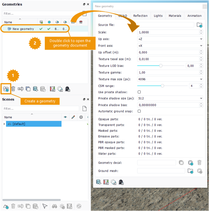
Creating a new geometry
After the renaming, open it by double clicking on the list entry. The first box named source file allows to select the resource. It can be a .RED file or a .FBX file.
The first panel contains general parameters of the geometry.
NDunes units are meters. The scale property allows to convert the source unit into meters. In the same way, the up axis and front axis of the source file can be set to convert to the NDunes axis system. In NDunes, the origin of the geometry should be on the ground. The up offset property translates the geometry so that the origin is on the ground.
Several properties affect the geometry textures: texel size, texture LOD bias and texture trilinear filtering allow to precisely define the mipmap selection and appearance. The texture gamma correction property is here to adjust the tint. At last, the texture max size property can be used to limit all the texture sizes. This is very useful to control the memory usage of the geometry.
Note:
To avoid Moiré pattern on geometries with high frequency textures, the texel size must be correctly set as the average size of a texel in meter. For instance, if a diffuse texture width is 2048 pixels and is mapped on a 2 meters long object then the texel size is 2 / 2048 = 0.000976.
The automatic ground snap property "locks" the geometry on the landscape. This is why the geometry origin should be set on the floor via the up offset property.
The last section of the panel shows the geometry statistics. A geometry is divided into several types of materials:
- opaque parts: default material, single-sided, no transparency;
- transparent parts: transparency material;
- masked parts: double sided material with alpha masking;
- emissive parts: you guess;
- PBR opaque parts: PBR material, single-sided, no transparency;
- PBR masked parts: PBR material, double sided with an optional mask;
- water parts: special material used with the water bodies. See Waterbodies.
The statistics show the number of geometry parts in each category, the number of triangles and the number of vertices.
Once the first panel is well setup, drag'n drop the geometry into the main scene to display it. The drop position defines the geometry position on the planet. Multiple drag'n drops of the same geometry create multiple instances.
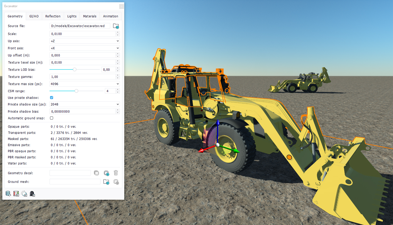
View of the geometry after drop
First remark: in the shadow regions, the geometry is fully black. Don't panic! The next page will show how to had indirect lighting with a global illumination cache.
 Geometries Geometries | Decal linked to the geometry |
